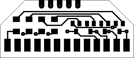
![[XA1541 mini-adaptor]](xa1541map.png)
You definitely need BSV52 transistors and 4.7 kOhm resistors for this adaptor, different parts may make the adaptor inoperable.
This is a double-sided board that needs to have the two sides connected via conductive material inside the drilled holes: through-coppering.
You need the following parts to build this adaptor:
One solderable 25-pin male plug (PC parallel plug)
One printable circuit board of about 4 x 2 centimeters
Four BSV52 transistors
Four SMD 1206-style 4.7 kOhm resistors
Step 1. Build the board of the adaptor, cut it to shape and drill the holes in it, according to the board diagram (300 DPI resolution): top side and bottom side. Both diagrams show the board as viewed from that particular side. Use through-coppering to connect the two sides through the holes.
Step 2. Build the amplifier bridges, consisting of one transistor and one resistor each, onto the appropriate places. These include the following connections:
| Parallel plug | Parallel plug |
|---|---|
| 13, Select | 1, Strobe |
| 12, PaperEnd | 14, AutoFeed |
| 11, Busy | 17, SelectIn |
| 10, Ack | 16, Init |
The collector of each transistor should be pointing towards the pin in the left column of the table. The base of each transistor should be connected to one side of the resistor; the other side of each resistor should be connected to the pin in the right column of the table. The emitters of the transistors should be connected together to the common ground of the adaptor.
The parts should be soldered the following way onto the board. This diagram shows the top side of the board as viewed from above.
Step 3. Solder and then glue the board between the two pin rows of the parallel plug. The top side of the adaptor, the one with the electronical components, should be leveled with the longer side of the parallel plug, the one with 13 pins.
![[XA1541 mini-adaptor]](xa1541mac.png)
You can find the description of all parts used on the diagrams at the legend page.
Contact |
Copyright and license |
Blog page | Recent updates |
Title page
(This page best viewed with any browser)