This is a double-sided board that, instead of through-coppering, connects the two sides via the pins of the IC's pulled through the drilled holes. Therefore, you will have to solder all pins of both IC's to both sides of the board.
On circuit diagrams, plugs are displayed as viewed from the back side, the solder side. Chips are displayed as viewed from above; also, see the small semicircular cut for finding the correct orientation. When in doubt, see the corresponding description on the legend page.
You need the following parts to build this adaptor:
One solderable 25-pin male plug (PC parallel plug)
One printable circuit board of about 4 x 2 centimeters
One 7406 inverter IC
One 74LS86 exclusive-OR IC
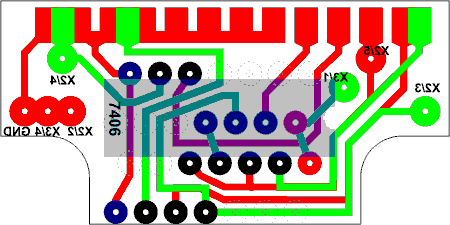
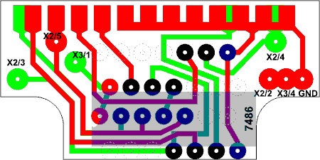
Step 1. Build the board of the adaptor, cut it to shape and drill the holes in it, according to the board diagram (300 DPI resolution): top side and bottom side. Both diagrams show the board as viewed from that particular side; green wiring corresponds to the top side and red wiring to the bottom side.
Step 2. Cut off the unused pins of both IC's so that they don't hang loose around, annoying you during the soldering. This includes pins 1-4 and 8-9 of the 7406 inverter IC and pins 1-3 and 8-10 of the 74LS86 exclusive-OR IC.
Step 3. Place the 7406 inverter IC onto the top of the board, push its pins into the drilled holes and solder one pin row to both sides of the board. Make sure to align the IC properly, with the help of the small semicircular cut that is also shown on the board diagram. Pull the IC upwards, slightly bending its already soldered pins, so that you can access the holes under the IC.
Step 4. Place the 74LS86 exclusive-OR IC onto the bottom of the board and solder it completely to both sides of the board. Make sure to align the IC properly, with the help of the small semicircular cut that is also shown on the board diagram.
Step 5. Bend the 7406 inverter IC back and solder its other pin row to both sides of the board.
Step 6. Solder and then glue the board between the two pin rows of the parallel plug. The top side of the adaptor, the one with the 7406 inverter IC, should be leveled with the longer side of the parallel plug, the one with 13 pins.
You can find the description of all parts used on the diagrams at the legend page.
Contact |
Copyright and license |
Blog page | Recent updates |
Title page
(This page best viewed with any browser)